final project
introduction
Here, I document my progress with my final project, from proposal ideas to final execution and presentation. Follow along on my journey through the course, and how I use the knowledge I gain in the course and apply it to my final project.
the project
demonstration and highlights
Here's my demo video, followed by the final parts and code snippets used. Enjoy!
the video
Enjoy the video! Here is the link to the video on YouTube.
Below is a brief description of the final hardware and software products.
the final components
Here are the finished components I used, both hardware and software.
hardware
Here are the images of the 3D printed components, includings downloadable STL files.
For thorough documentation on how I made them, scroll to the process below. These were modeled in Fusion360, sliced in Ultimaker Cura, and printed by an Ender 3 Pro. Downloadable STL file links on the way. The links are broken, attempting to fix them!
software
Here is the code I used to power this, Arduino.
                  //==============================================================================================================//
                  //--------------------------------------------- DEFINING VARIABLES ---------------------------------------------//

                  /*STEPPER MOTOR PINS AND CONTROLS*/
                  #define EN 8                  // enable end of stepper motor, active low
                  #define X_DIR 5               // x-axis stepper motor direction control --> feeding mechanism
                  #define Y_DIR 6               // y-axis stepper motor direction control --> bending mechanism
                  #define Z_DIR 7               // z-axis stepper motor direction control --> NOT necessary for 2D wirebender
                  #define X_STP 2               // x-axis step control ---------------------> feeding mechanism
                  #define Y_STP 3               // y-axis step control ---------------------> bending mechanism
                  #define Z_STP 4               // z-axis step control  --------------------> NOT necessary for 2D wirebender

                  /*CONVERTING BETWEEN STEPS AND REAL-WORLD MEASUREMENTS*/
                  #define STEPS_PER_DEGREE 0.8 // number of steps per one degree (calibrated during test runs)
                  #define STEPS_PER_MM    8.62  // number of steps per one millimeter (calibrated during test runs)

                  //---------------------------------------------- HELPER FUNCTIONS ----------------------------------------------//

                  // low-level step control
                  void step(boolean dir, byte dirPin, byte stepperPin, int steps) {
                    digitalWrite(dirPin, dir);
                    delay(50);
                    for (int i = 0; i < steps; i++) {
                      digitalWrite(stepperPin, HIGH);
                      delayMicroseconds(8000);
                      digitalWrite(stepperPin, LOW);
                      delayMicroseconds(8000);
                    }
                  }

                  // BEND FUNCTION: bend the wire a certain angle in ONE direction (single pin on wirebender)
                  void bend(int angle) {
                    step(false, Y_DIR, Y_STP, angle * STEPS_PER_DEGREE);
                    step(true, Y_DIR, Y_STP, angle * STEPS_PER_DEGREE);
                    delay(50);
                  }

                  // FEED FUNCTION: feed the wire a certain length forward into the bending mechanism
                  void feed(int len) {
                    step(false, X_DIR, X_STP, len * STEPS_PER_MM);
                    delay(50);
                  }

                  // POLYGON FUNCTION: bend a 2-dimensional CONVEX polygon with a certain number of sides and a given side length
                  // CONVEX because single pin on wirebender
                  // NOTE: only produces REGULAR POLYGONS by definition
                  void polygon(int sides, int sidelen){
                    int angle = 360 / sides;
                    for(int i = 1; i <= sides; i++){
                      feed(sidelen);
                      bend(angle);
                      delay(50);
                    }
                  }

                  //-------------------------------------------- SETUP AND EXECUTION ---------------------------------------------//

                  // SETUP: Set the IO pins used by the stepper motor as outputs
                  void setup() {
                    pinMode(X_DIR, OUTPUT); pinMode(X_STP, OUTPUT);
                    pinMode(Y_DIR, OUTPUT); pinMode(Y_STP, OUTPUT);
                    // pinMode(Z_DIR, OUTPUT); pinMode(Z_STP, OUTPUT);  // 3rd dimension, not necessary for 2D wirebender
                    pinMode(EN, OUTPUT);
                    digitalWrite(EN, LOW);
                  }


                  // MAIN LOOP: test polygons
                  void loop() {
                    //feed(100);
                    polygon(7, 30); // heptagon of side length 30 mm
                    delay(1000);
                  }
                  //==============================================================================================================//
For thorough documentation on how I coded this and how I calibrated the hardware, scroll to the process below.
For more info on how I made this, scroll to the process.
This concludes the demo. For thorough documentation on the process, scroll down, and for documentation on other lessons, go to other links. I hope you enjoy!
the process
proposal(s)
At the beginning of the course (and even through to around week 3), I was juggling a few proposals. I wanted a balance between ambition, practicality, and usefuleness. In other words, I wanted to create something that would actually be useful and practical, while also create something I am proud of and find interesting, all while not going completely insane trying to actually execute the idea.
proposal 1 -- cars
My first proposal stemmed from an issue that I personally find myself in (well sort of), and one that I believe a lot of people also suffer from: being able to tell whether or not you will be able to fit your car into a given parking space. I see my dad constantly wasting a lot of time looking behind him to try to see if he could fit our car into a parking space. Sometimes, he decides he can't, and we drive off, many minutes wasted for potentially no reason. So I thought to myself: what if he didn't need to do that himself. And so, my first proposal was born: a device with a camera and sensor that you can plant on the back of the car that would be able to, given the car's dimensions and distance from a given parking space, whether or not your car could fit into the parking space in question. I quickly scrapped that idea, however, as I did not feel that it would be practical to build and code such a contraption to reliably (and consistently) work in 7 weeks at my skill level.
proposal 2 -- lamps
This next proposal involved something a little bit simpler: lamps. I really liked Harry Potter as a kid, and I had visited the Wizarding World of Harry Potter in Orlando a few years back. Butterbeer may have been the tastiest part of the trip, but the wands that could be used to control various lights and aspects of the park were certainly the coolest. So, I thought: why not do the same with the lights in a house? And so, my next proposal was to wire a circuit that could communicate with the lights in a house, and with various gestures of a wand with a signal sender, receive that signal and perform a variety of tasks, such as turning the lights on or off, toggling the brightness, and even the color.
proposal 2.5 -- useless box
This wasn't really a "new" proposal to replace the previous one, as I was tossing around a few ideas at once. I really like the idea of "useless boxes", ie boxes where, if you push a button or flip a switch, a little hand or figurine will pop out of the box to do nothing but push the button again or flip the switch back to neutral position. Many have made these types of boxes, and some have even created skits with these boxes, where they coded the box's reaction to "evolve" the more times the button was pressed or the switch was flipped. This is where I came up with another proposal as a slight modification to the useless box: a useless box with facial expressions (made from LEDs) that evolve to a more angry state the more the button/switch is pushed/flipped, as the box gets progressively more "annoyed" at the individual.
I would spend a considerable amount of time trying to decide between the last two proposals, as I was flip-flopping back and forth for a variety of reasons. I was focusing on practicality, range of possibility, and my own ability to create them to a reasonable extent in 5-7 weeks.
finalizing the proposal
After sitting on it for a few weeks, I finally decided between the two proposals I was working with, though I did add in a slight modification to it.
the final proposal
My final proposal for the final project was the lamp idea, where I would wire a few boards to receive signals sent by (or reflected by) a wand, which would correspond to a precoded command. Instead of one phototransistor or sensor being able to tell apart gesures, I decided to simply wire 4 different phototransistors, each responsible for something different and being able to tell one gesture: two would be for turning the lights on and off (respectively), and the other two for toggling the brightness (increasing and decreasing, respectively). This final proposal was finalized on Monday, 19 July, 2020, after an extensive discussion with Nathan during the 17:00 lab section on 13 July, and some personal thought/consultation afterward. This was to avoid using different gestures.
After also consulting my mom following the lab, I also considered potentially including an option to toggle speakers to play music, though this is still only a theory, and I will only implement it if time permits.
With the proposal finally set, I was ready to start thinking about how to actually implement this project, and also ready to start drawing up some basic plans for the code and (simplistic) hardware. That is, until I had a sudden and last-minute change of heart...
sudden developments: a last-minute modification
While working through the class 10 assignment, I was struck with a new idea for a final project, one that was so mesmerizing that I decided to completely scrap my original final project idea in favor of this new one. I decided to work instead with wirebending. After a lot of consideration, I finally decided to scrap the initial proposal in favor of a complete rework of my final project.
the (true) final proposal
This completely overhauled final proposal involves creating a 3D wirebending mechanism which can move in multiple dimensions. I would be able to control this mechanism from my computer and through a remote network, and if I give it specific commands and parameters, it would be able to bend copper wire into any configuration I tell it to bend into. I could potentially have a few precoded designs and shapes that I could use to demonstrate the results of this mechanism during the presentation. This modification and new proposal was drafted and finalized on the morning of 28 July, after a lot of contemplation during class 10's assignment.
This modification to the proposal came, again, as a result of class 10's assignment that I was working on, which involved a 2D wirebending mechanism. More information and thorough documentation can be found in the class 10 tab above. This was also approved by each of the instructors, and they liked this new proposal, and found the video demonstration I linked on my page of an example 3D wirebender "very mesmerizing". While such a last-minute change did sound very troublesome, I found that as long as I built off the results of the class 10 assignment, I would rather easily be able to abstract to a 3rd dimension of motion.
Now, with the proposal finalized (for real this time), I was ready to start working on this new final project (and subsequently scrapping the initial project which I had already started working on).
planning out the (eventually scrapped) lamp proposal
Here, I detail some of my basic plans, and the progression of the plans into something that I can implement. I went through several drafts of plans, each getting more and more detailed, and each one detailing specifics. Eventually, with the final plan, I am ready to implement the plans into a real project.
the initial plans
Here, I post my initial and rather general plans for the entire project. They each get slightly more detailed, but are still fairly general.
draft 1
This was the very first plan I drafted after the proposal was finalized. It contains rudementary explanations of what I planned on doing with the project, and how it would work.
The plan is simple: Have an IR LED send a signal that would be reflected by a wand into one of 4 phototransistors, each responsible for one action (turning on the lights, turning them off, increasing the brightness, and decreasing the brightness). These would send a signal to the lamp(s), making them do what you'd like. It also lists what I need, and what I've acquired already. Finally, I included a crude basic design for a possible case for the mechanism (for prettying purposes), and the functions I'd need to define. I would make edits later, after some discussion with Nathan and Victoria on how to make only some of the lamps perform certain tasks.
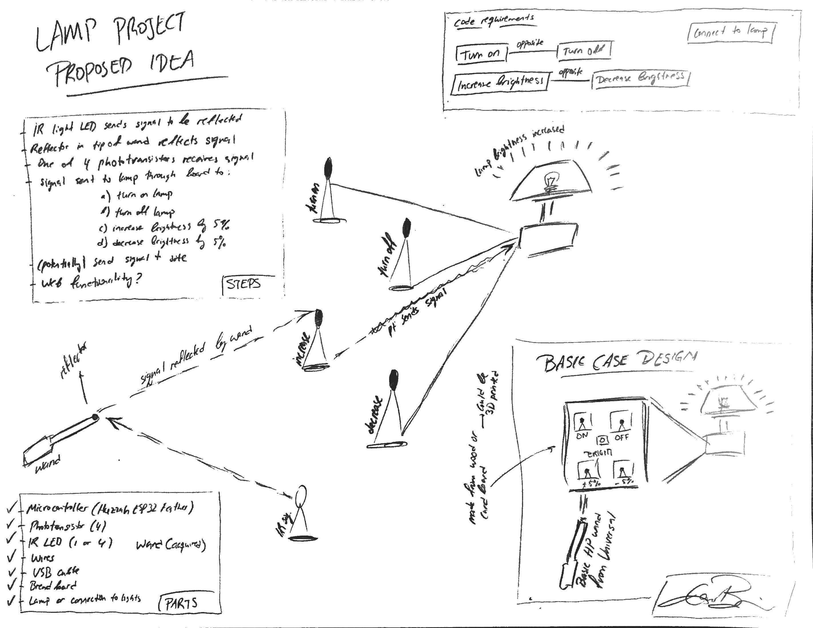
This was the first plan, and the second one gets a little more detailed and more specific. I add on to the proposal after discussion during the breakout rooms, but here was the rough first draft. It included a very basic plan.
completely scrapping this idea
As I listed in the above section on proposals, I eventually, with class 10's work, proceeded to completely scrap this plan in favor of the 3D wirebending proposal. So, even though I had a lot of plans for the creation and execution of this project, I liked the other one much more, and felt that I was much more ready to create that one with the progress on the 2D mechanism already.
Even though these plans were great and I had a lot of ideas about this project, I felt that scrapping it for the new proposal was ultimately the right decision, as it is something that I would be prouder of and something that I would be able to use more for fun and something that would be quite fun to play with.
Despite the fact that I had scrapped an idea that I spent a lot of hours thinking about and planning, I deemed this ultimately for the best, and I was eager to get started with this new final project idea. While it would be daunting and require more time and thought and planning, I was excited to get started with it and work through it.
planning out the wirebender
It was now time to plan out this new proposal before executing it. I would need to plan this extensively to simplify the work process later on during the project. This entire section will detail thoroughly all of the planning that went into this proposal.
class 10's assignment: 2d wirebender
To start out, I needed to get the 2D wirebending mechanism to work. This entire final project proposal was inspired by my class 10 assignment, which involved developing a 2D wirebending mechanism with 2 stepper motors and a few 3D printed parts. As soon as I knew I could get this mechanism to work, I knew 'upgrading' to 3 dimensions would not involve that much extra work.
the wirefeeding mechanism
The first step was figuring out how the wirefeeding mechanism worked. I would have to feed a wire in a straight line and at a constant rate into the wirebending part in order for the wire to even be able to bend at all. More thorough documenation of the planning (and eventual execution) of this step can be found on the class 10 tab above, under the subsection under the same name found in the assignment section at the bottom of the page.
the results
Here are the results I produced for this mechanism. The same results can be found in the class 10 assignment section, but I linked the results here as well. This now smoothly feeds wire through the mechanism to the wirebender, keeping it taut and preventing slipping, allowing for smooth feeding. This would come in handy for the actual final project, as it is a vital part of any automated wirebending mechanism.
I was now ready to move on to the next part of the build. As always, more thorough documentation can be found in the class 10 page, as this is directly following my class 10 assignment.
Even though this was used to feed wire into a 2D wirebending system, the mechanism would work the exact way for 3D system, thus no further edits or changes were required for this mechanism. Thus, a good chunk of the final project is already complete.
the wirebending mechanism
The second step was designing the actual wirebending mechanism. I started with the simplest 2-dimensional one, to truly understand how to create a wirebender. This mechanism would receive a wire fed from the wirefeeding mechanism, which would then bend the wire at given points, depending on the parameters specified in the code that would supplement the hardware. Thorough documentation of the manufacturing process can (again) be found in the class 10 page linked above, but I still have a demonstration of the results below.
the results
Here are the results produced with this wirebending mechanism. This goes hand-in-hand with the wirefeeding mechanism, and I can now successfully code it to work remotely and bend whatever shapes I like, so long as they are 2-dimensional.

With this complete, the wirebending part of this system was complete, and they could be put together and coded to work.
This mechanism could now be put together with the rest of the system to produce the full wirebending system.
With that work out of the way, the class 10 assignment, otherwise known as the 2D wirebending system, was complete. This now allowed me to bend wire into any 2-dimensional shape I liked. I needed now to take this one step further, so that I could create 3-dimensional shapes.
transitioning to 3d wirebending
The last bit that remained for this project was to upgrade this system to move in a 3rd dimension. This would be the final step, and as soon as I figured out how to do this, I would be able to proceed with building and completing this project. This involves a third stepper motor that would be able to move the 2D wirebending part in order to add another dimension of motion. Below, I have my plans for creating that 3rd dimension.
a little hiccup
Unfortunately, planning out/executing the 2D wirebender in its entirety was enough of a challenge, and getting the third axis to work without the whole system falling apart was not something I would be able to accomplish in the limited time I had to complete this project. Thus, I settled on creating a nice little enclosure for the 2D wirebender, prettying it up, and coding some fun little shapes for it to produce. I got the OK from Nathan and Victoria to pass this off as the final project, but I was still sure to implement the 3D bender in the future.
While I wasn't able to get the whole 3-dimensional bender to work for the final project, I was very excited to see how I could finish it off on my own after the course ended, as were all of my instructors. Thus, even though the 3D bender won't be a complete version of my final project, it is definitely something that I was going to pursue on my own time after the course had ended.
With these plans complete, I would be able to transition into building, coding, and executing this final project idea. The planning was the most vital and crucial step, because as long as I understand exactly how to implement what I'm doing, I am able to implement it without that many general hiccups.
designing/building the wirebender
Here is where I document my progress with building and executing my project. Now that I have officially finished with the planning, I was ready to move on to actually making this proposal (and these plans) a reality.
the hardware
Here, I detail everything regarding the hardware. Since I had everything planned out, I was ready to start experimenting with how the hardware will come together and work to bend wires in 3 dimensions. I used Fusion360 for the modeling, Ultimaker Cura for the file slicing, and an Ender 3 Pro 3D printer for the printing.
3d printer shenanigans
To make this final project (specifically the hardware), I knew that I would have to get my hands on 3D-printed parts. Hence, it was only logical that I would buy and assemble an Ender 3 Pro 3D printer. Below is a timelapse of me assembling it.
I would also use this printer to get all of the 3D-printed parts that I needed for this hardware. More info on that modeling is listed below.
the final plans
Here are all of the final plans that I would use to create the models, program, and assemble the rest of the project.
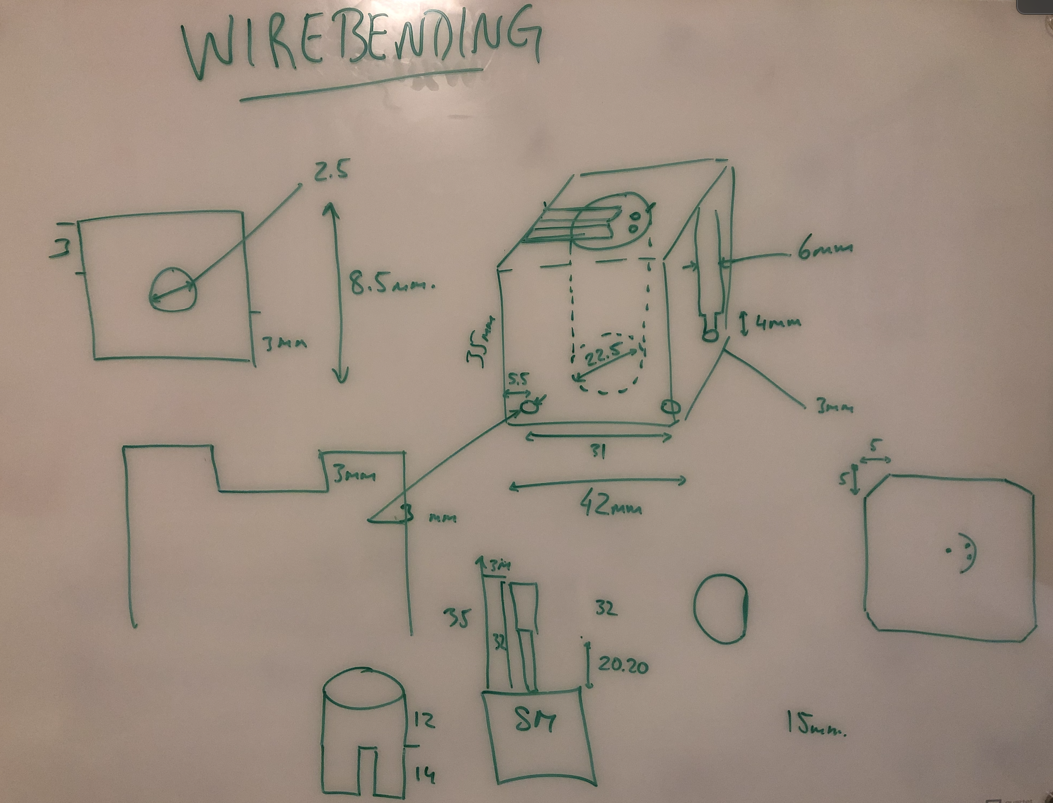
With all of these plans complete, I was able to now apply those blueprints and create the necessary models in Fusion360 that could then be sliced by Cura and printed by the Ender 3 Pro. I would also now know exactly what to program for the stepper motors, so I would be able to program the bending mechanism to work once I could assemble the hardware.
the models
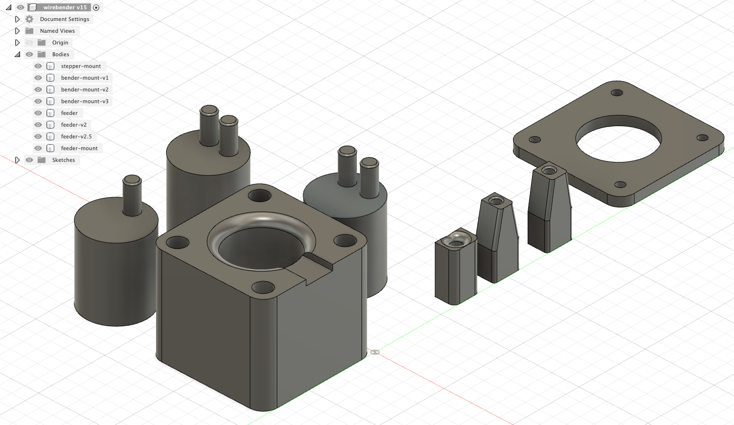
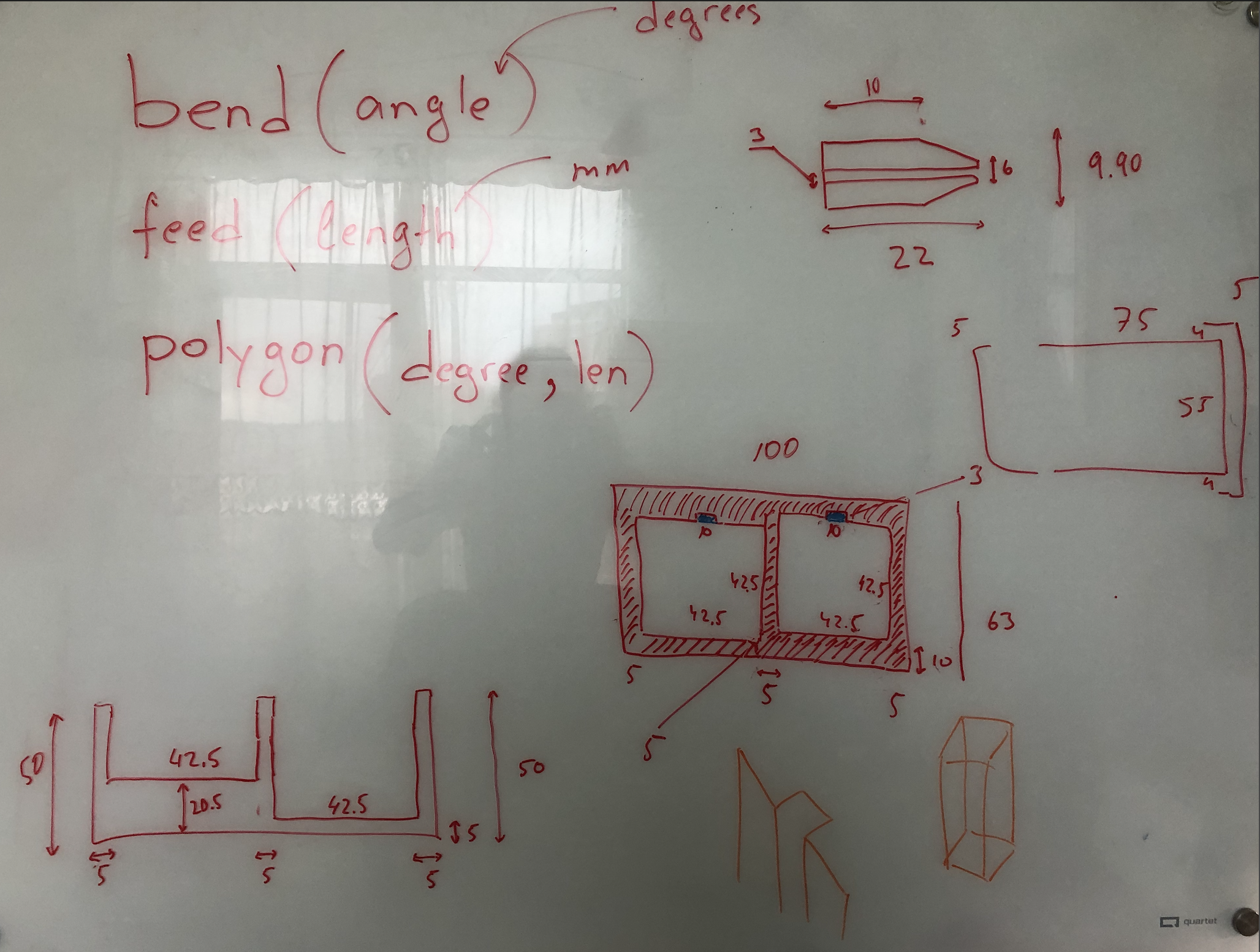
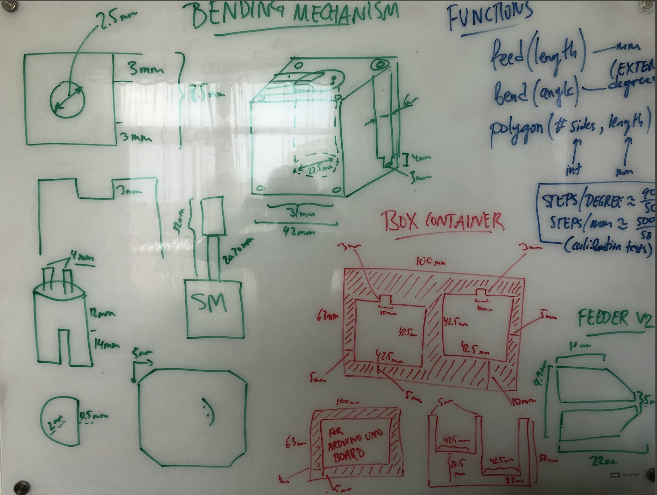
I needed to design a few things: the wirebending mechanism and the box container. The wirebending mechanism consists of the mount (that goes onto the outer hull of the stepper motor), feeder (that mounts on top of the mount), and bending apparatus (that sits on the stepper staff thingy).
the mount
The mount was the simplest part, as it simply had to match the rough dimensions of the stepper motor, with a hole in the middle for the bending apparatus. I modeled it in Fusion360 fairly quickly.
the feeder
Another important part to get done was the little feeding mechanism that would mount on top of the stepper mount. The wirefeeding mechanism would feed wire into this little hole, which would then feed the wire in a straight line to the bending apparatus. It was important to get these dimensions right, but it still took a short amount of time.
the bending apparatus
The final part of the bending mechanism was the bending apparatus, which mounts on the interior part of the stepper motor and will actually bend the wire. The most annoying part was getting the hole just right for the apparatus to fit snuggly onto the stepper motor with little-to-no wiggle room. I created several versions of this: one with two stubs, a replica of that with more spacing between the stubs, and one with a single stub.
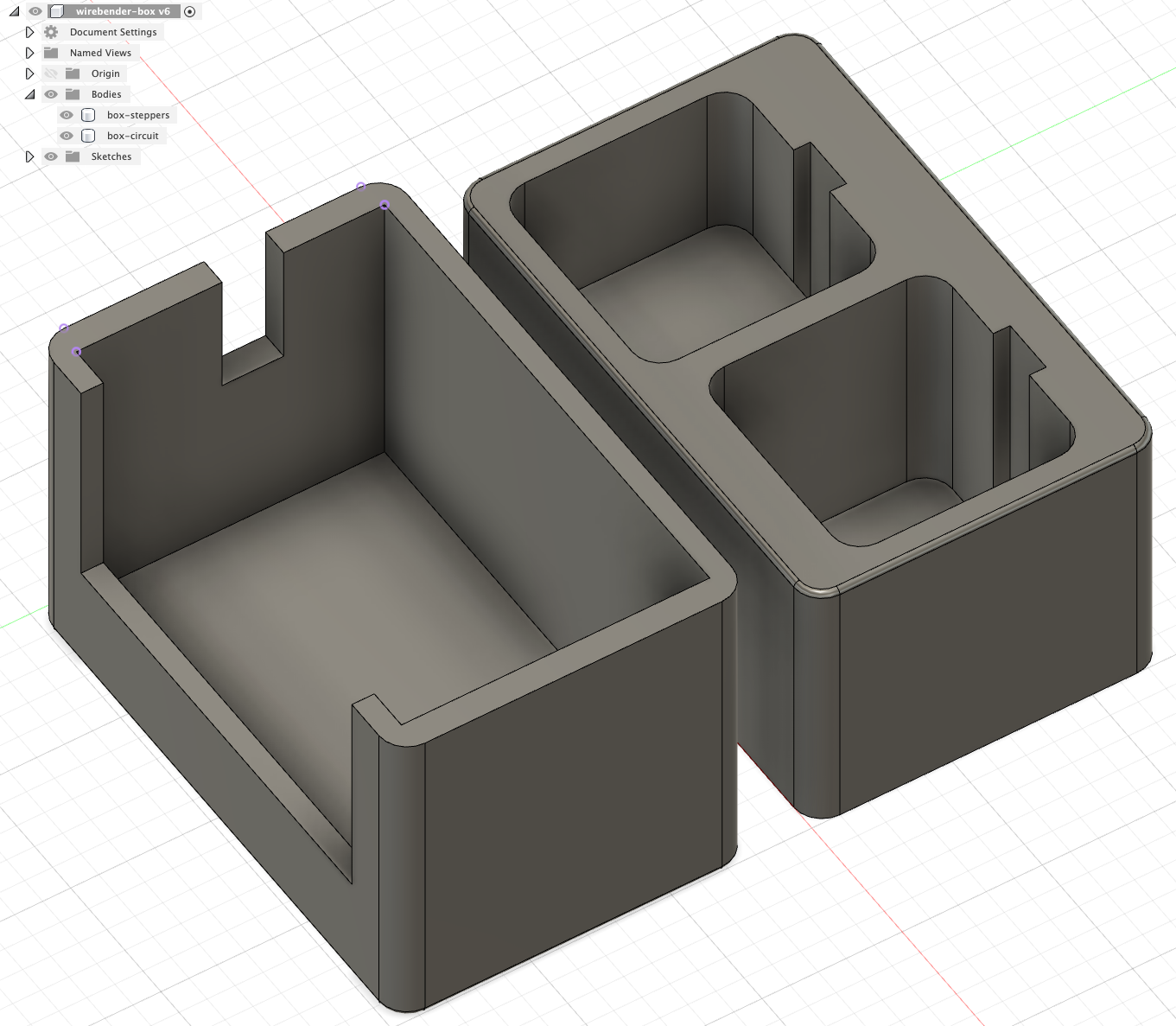
the box
Finally, I wanted to make one little box that would house the whole ensemble in a small, clean fashion. I needed the stepper motors to fit snuggly into the holes so that they did not move, as well as leave some room for the wires to come out of the motors and into the circuit board. This was on the simpler side, but still required precision to nail. Seeing also how this was the most time-consuming print (8.5 hours), I needed to essentially nail it on the first try.
Overall, the models were fairly nice, and they printed well and assembled exactly how I wanted them to. All of these are visible in the above window and in the downloadable STL files.
the circuit
Wiring the circuit wasn't that bad, as I found an exemplar online and followed it to the letter to make sure my board functioned how I wanted it to. The wiring can be seen below.
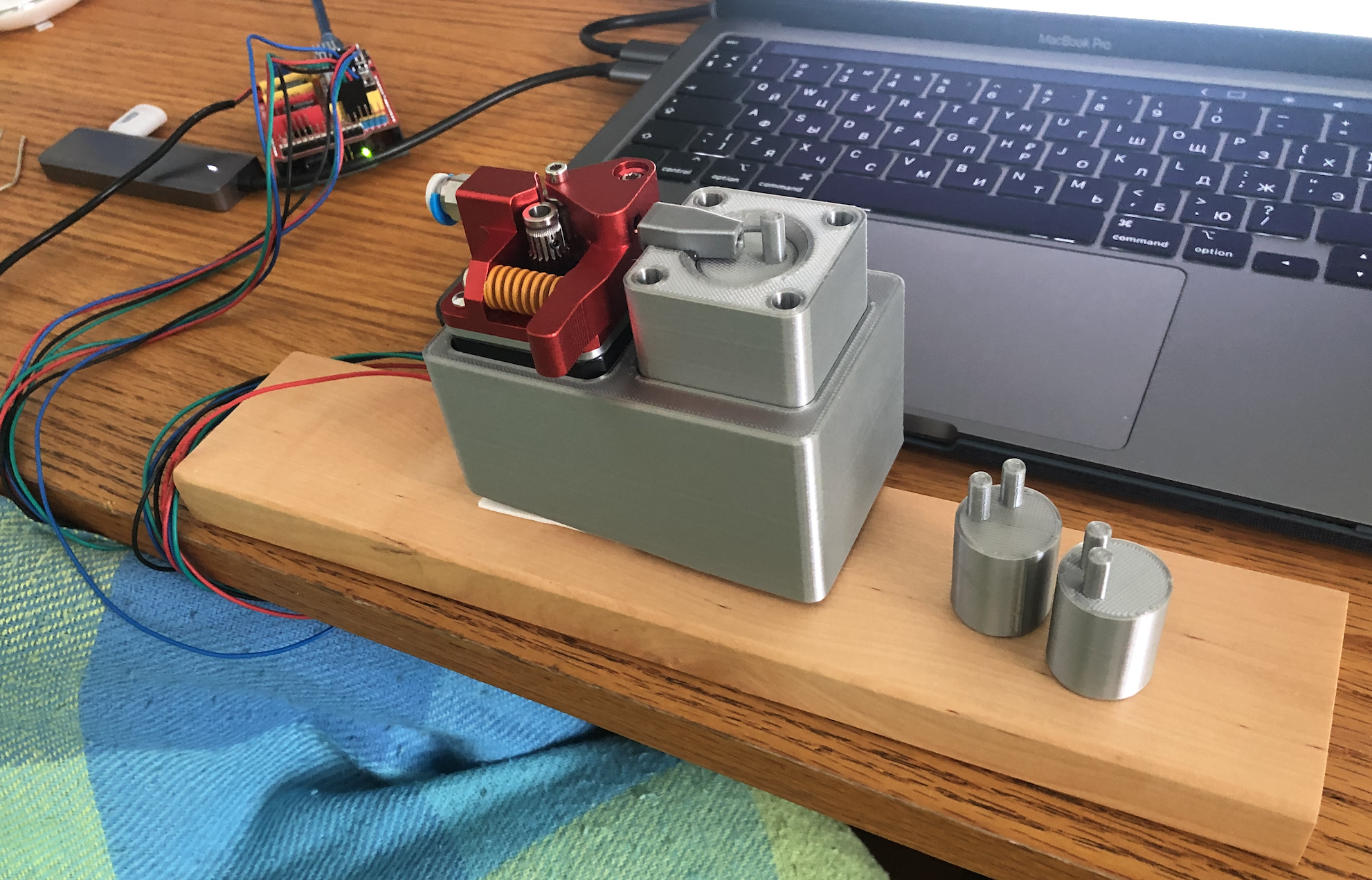
the assembly
Now, all that was left was to put it all together, and myhardware would be complete. Below is a picture of the assembled wirebending mechanism, which completes one important half of the project.
As soon as the hardware was complete, I was able focus more of my attention on completing the software aspect, though I was working on both of them sort-of simultaneously. This hardware, though, was certainly the most time-consuming aspect, with the planning, modeling, printing, remodeling, reprinting, and assembly.
the software
Here, I detail everything regarding the software. Since I had everything planned out (just like with the hardware), I was redy to start experimenting with how the software will power the existing hardware and culminate in a 3D wirebending mechanism that can create any 3D shape out of wires that I want (and that are possible). This software, while not as time-consuming as the hardware, was definitely the more technical aspect of the project. All of this code would be completed in Arduino.
making the motors work in tandem
Getting the feeding mechanism and the bending mechanism to actually both work in tandem and not destroy each other was the most integral part to getting this mechanism to work. As soon as I was able to make sure that they could work together, then I could define degrees in terms of steps, and I would be able to then program the bender to bend shapes for me. After extensive scouring and personal edits, I found/modified this block of code that inevitably allowed me to control the two motors together. Below is the code, along with a video demonstration.
                  #define EN 8      // Enable end of stepper motor, active low
                  #define X_DIR 5   // X axis stepper motor direction control
                  #define Y_DIR 6   // Y axis stepper motor direction control
                  #define Z_DIR 7   // Z axis step motor direction control
                  #define X_STP 2   // X axis step control
                  #define Y_STP 3   // Y axis step control
                  #define Z_STP 4  // Z axis step control

                  void step(boolean dir, byte dirPin, byte stepperPin, int steps) {
                    digitalWrite(dirPin, dir);
                    delay(50);
                    for (int i = 0; i < steps; i++) {
                      digitalWrite(stepperPin, HIGH);
                      delayMicroseconds(800);
                      digitalWrite(stepperPin, LOW);
                      delayMicroseconds(800);
                    }
                  }

                  void setup() {// Set the IO pins used by the stepper motor as outputs
                    pinMode(X_DIR, OUTPUT); pinMode(X_STP, OUTPUT);
                    pinMode(Y_DIR, OUTPUT); pinMode(Y_STP, OUTPUT);
                    // pinMode(Z_DIR, OUTPUT); pinMode(Z_STP, OUTPUT);
                    pinMode(EN, OUTPUT);
                    digitalWrite(EN, LOW);
                  }

                  void loop() {
                    step(false, X_DIR, X_STP, 100);       // X axis motor reverses 1 turn, 200 steps is one turn
                    step(false, Y_DIR, Y_STP, 50);        // Y axis motor Reverse 1 turn, 50 steps are one turn
                    step(true, Y_DIR, Y_STP, 50);         // Y axis motor forward 1 turn, 50 steps is a turn
                    // step(false, Z_DIR, Z_STP, 200);    // Z axis motor reverses 1 turn, 200 steps is one turn
                    delay(1000);
                    // step(true, X_DIR, X_STP, 200);     // X axis motor forward 1 turn, 200 steps for one turn
                    // step(true, Z_DIR, Z_STP, 200);     // Z axis motor forward 1 turn, 200 steps is one turn
                    delay(1000);
                  }
Now that I had these motors working in tandem (and now that I had funnily enough nailed exactly how many steps a 90 degree angle was), I was able to proceed with coding some shapes for the wirebender to bend. I would then show off one of these examples in my demo video and during the presentation of the project.
the code
Here I have the completed code for defining degrees and length.
                  #define STEPS_PER_DEGREE 0.8 // number of steps per one degree (calibrated during test runs)
                  #define STEPS_PER_MM    8.62  // number of steps per one millimeter (calibrated during test runs)

                  step(false, Y_DIR, Y_STP, angle * STEPS_PER_DEGREE);
With the definitions complete and the bender calibrated, I am able to now actually make the bender create shapes, which would finalize the project.
As soon as the software was completed, I was able to focus on bringing the hardware and the software together into a finished version of the final project. The hardware needed to more-or-less exist when I started finalizing the software, even though I had worked on them sort-of simultaneously.
putting it all together
As soon as I got the hardware and the software to work, I was ready to put it all together to create a working version of my project. The hardest parts were over, so I was ready to get started with finishing everything up. The assembly was quite fun, and the results can be seen in the demo above, as well as an image linkeed below.
With the building complete, it was time to create the demo video and prepare for the presentation of this project.
12: project prep
As a note, since essentially the entire class is spent on prepping for the final project and I really had no other work that I needed to do for this class that was separate from the project, I have simply included this section in this page for simplicity.
introduction
This section detais what I worked on (and learned) with class 12, held on 30 July, 2020. This is the final class for instruction, and we worked mostly on the final project here, so the page lives here for simplicity, as explained below.
wildcard class: miscellaneous topics
This class was treated as a "wildcard" class, as it was really meant to wrap up instruction for this course. A variety of topics were covered, all way too much for me to condense onto a simple documentation site, so all can be found on Nathan's and Rob's pages. These were quite interesting and fun to see, and while it's a shame that we did not get to these during the class, it's fun to see what could've been and fun to see how much more there is left to learn and discover in this world.
assignment/breakout rooms: final project work
The "assignment" for this final class was to keep working on the final project, which was also done during the breakout rooms. All documentation regarding what I did in preparation for this final project can be found anywhere in this Final Project page.
Not much was really actually taught as part of an assignment this class, as it was really meant more or less as a wrap-up of the course, as previously explained. All that was left now was to tidy up and finalize any documentation that needed to be finalized and complete/document the final project in preparation for the presentations on Thursday, 6 August.
preparing for presentation
The final step to this project, after actually creating it, was showing it off! I needed to do this in some form of demo video, as well as a presentation that would complement all of this. I needed to have that ready so that I was able to present this project on Thursday, 6 August at 15:35 EST. Here are all of my preparations for that. The final result of the demo video can be found above in the demonstration section preceeding all of the documentation on the process, and the presentation was recorded and can be accessed here (broken link).
the demo video
Here I have everything pertaining to planning out, preparing for, filming, and editing the demo video that can be found above. This is meant to serve as a very brief demonstration of my final project, what it does, and some highlights regarding how it works/ how I put it together.
the plan
The plan was simple: I wanted to incorporate all aspects of the project process and results into this one-minute video. Since this project involved planning, modeling/printing, coding, and execution, I wanted to reserve time for each of those aspects in the video. Thus, I decided that I would open with the bender doing its thing, then pan/cut to the bluprints that I all rewrote/reformatted on the whiteboard next to me. After this, I would transition to the secondary monitor I have mounted on my desk, where I would show the 3D models in Fusion360 and then move to one of the components in the Cura slicer. After that, I would cut to my main monitor on my laptop, which would display the Arduino code, and finally cut back to the wirebender finishing up a polygon it was bending out the entire time. I would then overlay it with music, as I wanted the video and the images to speak for themselves.
the filming
I enlisted my dad and his (more professional) filming expertise/equipment. We filmed each of the aspects listed in the plan separately, with the bender and code filmed in one part, and the plan/models filmed in another part. With the filming done, we then needed to edit it together to make it look like what I wanted it to look like.
the editing
With all of the filming complete, it was important to cut it together in the right order with the right durations and transitions, and then overlay it all with some fun and dramatic music. I once again enlisted my father and his Adobe Premiere Pro license to get this editing done.
software used
As stated before, given that my father had a functioning Premiere Pro license and a working knowledge of basic video editing, he helped me cut togehter (and speed up) the clips in the order I desired.
the actual editing
The actual editing was fairly straightforward: arrange the clips in the right order, cut unnecessary chunks, add transitions between clips to reduce jarring changes, mute all the audio, and overlay the last minute of an Itzakh Perlman recording of Tchakovsky's Violin Concerto in D Major. The results speak for themselves.
Since I didn't have that much editing experience, I knew I would need some help, and I am very grateful that I had the resources and people I could turn to for this final part of my final project for this course.
Overall, it was a fun process to make this video, as it was really all window dressing at this point. I still liked the results, and they can be seen both on YouTube (unlisted video, link with the video above) as well as here (above with the demonstration section).
the presentation
It was also important to plan out exactly how I was going to spend the 5 minutes I had to show off my final project and everything I could regarding it, so this is exactly where all of that information lives. The recordings for the presentation (as well as everyone else's presentation) can be found here (broken link). I wanted to show off the demo video, and then take some time to delve into each aspect shown in the video (which would essentially cover the bulk of the process, excluding all of the excruciating hours and lost brain cells), leaving about a minute for personal reflection and Q&A. I wanted to demonstrate my utmost interest in the course and the project with that presentation, and given my years in debate, I'm happy to say I was able to come up with a basic outline for that presentation and deliver it how I wanted to.
This has been a very fun course, and I certainly learned a lot about designing/creating hardware, coding software, and prototyping/executing creations that I have in mind. It was a very interesting exploration of practical applications of physics, and it was definitely one of my favorite hands-on experiences in a classroom/learning environment!
future possibilities
There are plenty of future possibilities for this project and for where it can go! The biggest plan that I had was to complete the 3rd dimension and create the 3D wirebender, as I wanted to with the this. The plan here would be to design a little housing and anchor to move the 2-dimensional bender with the third stepper motor without breaking anything. I did not really have time to complete this for the final project of this course, but this is definitely something that I want to pursue on my own time and complete after the course finishes. I am excited to get that 3D bender to work!
thank you!
Many thanks go out to Nathan, Rob, and Victoria for being amazing teachers and helping me every step of the way, as well as all my classmates for being amazing people that have such incredible imaginations! Thanks also go out to every single resource I used when working through this course. This is definitely a course that I would recommend to anyone interested with a hands-on experience, and I am sure anyone who takes it will enjoy the laid-back but nevertheless rigorous course. While I wish I could've done it at Harvard University in person, I am still happy with what I got.
final message: 10 august, 2020
As of 10 August, 2020 (the publishing of this final bit), all documentation of this website has been finalized, and no further documentation will be added to this website. No additional photos, videos, code snippets, models, or commentary will be posted to this site. This website is meant to serve as the documentation of my learning during the Introduction to Digital Fabrication (PHYS S-12) course during Harvard Summer School 2020, and the program officially ended on 10 August. Thus, this website will no longer be edited and nothing will be added to it. This is why my biographical information may no longer be accurate at the time of reading of this page. It has been a fun run, but sadly, the course is over, and thus my documentation is also complete. Thank you to anyone and everyone who helped me along the way, and I am excited for future endeavors!