10: machine building
introduction
This page describes what I have learned with class 10, held on 23 July, 2020. During this class, we focused a little more on the mechanical side of things, and learned more about stepper motors and how to drive them. We also had the opportunity to think more about our final projects, and start executing some plans involving that project.
understanding stepper motors
This class, we spent a lot of time understanding how stepper motors work and working on driving them. More can be found in the assignment tab below, which is an exploration of how to work with the stepper motor in what I think is a creative way. We worked on driving one stepper motor and then two stepper motors in our breakout rooms, and just learned a lot about the general functionality of a stepper motor. Controlling them through the internet came with configuring the FireBase project to include the stepper motor driving. Our stepper motors are bipolar, which makes them a bit easier to use, understand, and wire than unipolar ones.
breakout rooms: driving stepper motors/ machine-making workshop
In the breakout rooms, we did some practice of our own: first we wired up one stepper motor to our circuit and ran some test code to make sure one motor was moving, and then we wired up a second stepper motor and used a different code snippet to get those two motors to work in tandem. Getting multiple motors to move side-by-side would be crucial for what I had planned for my assignment (and by extension my new final project proposal, more info below and in the Final Project tab), so getting these breakout room experiments to work was crucial. As always, more info can be found on Nathan's GitHub page and Rob's GitHub page; the former contains more explanations of the theory and how it works, whereas the latter contains specific info on wiring and running test code.
assignment
For this class's assignment, we were supposed to create a computer/phone-controlled machine that incorporated at least one stepper motor. I had a lot of ideas, but I had to make it feasible and build it in the limited time I had.
2d wirebender
My favorite idea was to create a 2d wirebending mechanism, as the one described by Nathan during the class as an example for interesting applications of stepper motors. This endeavor proved to be a very difficult task, however, much more challenging than I had anticipated, but I worked extensively to get it to work. While this is less complicated than a wirebender that moves in multiple dimensions, it would still be a challenging task that I, admittedly, underestimated.
the plan
The plan was deceptively simple: create a wirebending mechanism by feeding/straightening a wire into a stepper motor that will then bend the wire by turning a certain number of steps with a certain cooldown period in between. This means I would need two different mechanims working together to get the wirebending machine up and running: a feeding mechanism, and a bending mechanism.
the feeding mechanism
The first part (and the most vital to get right) is the feeding mechanism. This mechanism simply needs to feed a straight piece of wire through at a constant rate into the bending mechanism. This part was the most challenging for me, as it required materials I didn't have, such as metal gears and an attaching mechanism to connect to the second stepper motor.
planning it out
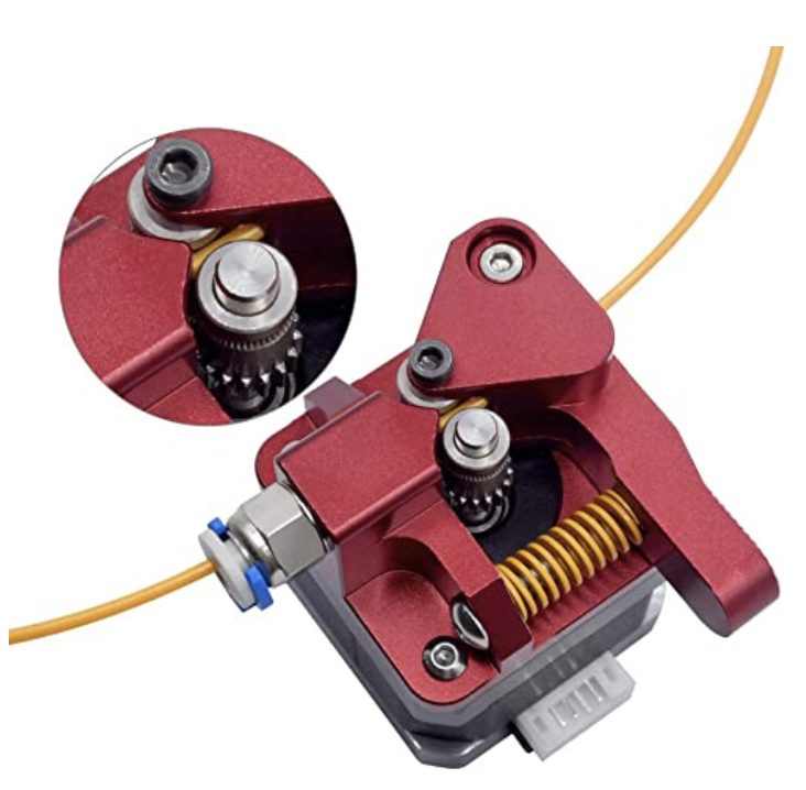
This took the most planning out of everything. I spent a lot of time researching the entire wirebending mechanism, specifically this wire feeding one. I researched a lot on YouTube and online to find wirebending (and wirefeeding) mechanisms that looked more or less "doable" in a short amount of time with limited materials, and found this video and this one as examples. The first one, after more research and looking at this page on the Arduino project board, involved too many 3D printed parts, and so I eventually decided to try to replicate the simpler one in the second video. After a lot of fiddling with the kit and researching more mechanisms online, I found exactly what I needed, which is actually a bunch of parts necessary to complete the mechanism connected to a stepper motor (link on Amazon right here). Below is an image of the exact mechanism that I would need to attach to the first stepper motor.
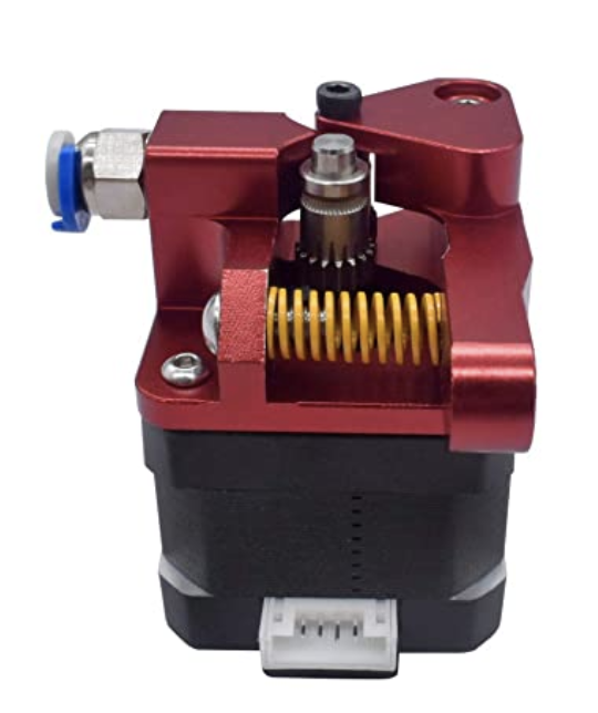
This mechanism is quite a simple one, as it simply involves pushing wire between two metal gears in a space enclosed with a compressed spring. This will keep the wire taut and will prevent slipping, which will continously feed the wire through to the next mechanism, which will actually bend it. Below is a breakdown of the components, and a demonstration of how the wire should feed through. As always, this can be found on the Amazon site I linked above.
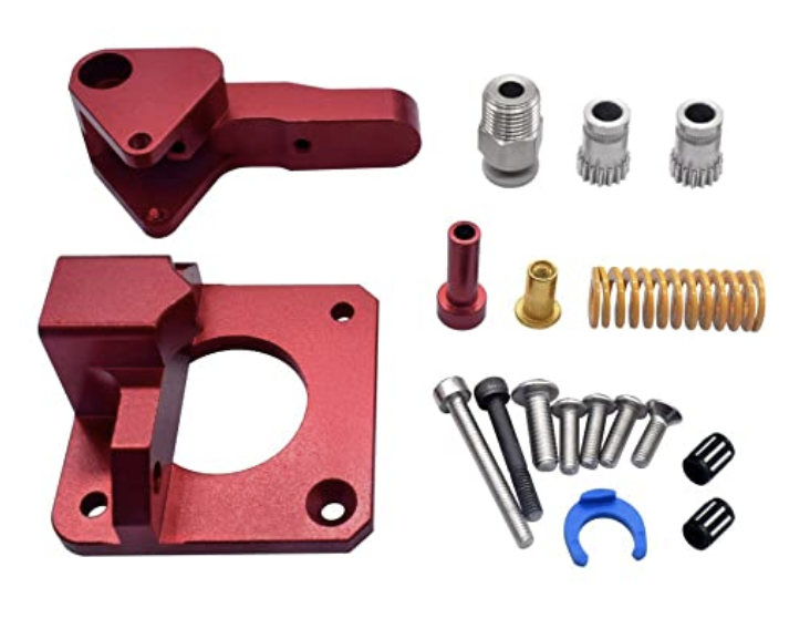
I decided to get these components online, because I did not have any of the proper gears or springs available to me at home. Without them, there would be too much room for error, and the wire would regularly slip and thus the bending mechanism would not work properly since the wire wouldn't be fed through correctly. This, I found, was the optimal solution.
getting the parts
As listed above, I initially planned on seeing if I could either get the parts from somewhere in my house or build them from scratch. Unfortunately, the parts I required are simply too precise to be created without either buying them at a store or 3D printing them. I then considered buying a 3D printer and creating the designs myself, until I found the exact mechanism I needed online (Amazon link above) and decided to just buy that. I then got and assembled an Ender 3 Pro 3D printer, created and modeled the parts, and printed them out.
the assembly
After the parts were able be to completed fairly smoothly, with only minimal edits requried to the designs when things didn't line up. that the assembly would be fairly self-explanatory and straightforward. The Amazon link even shows how it should be attached, so once I get it, creating it and assembling the mechanism shouldn't be too difficult.
This was definitely the most time-consuming step, as it required a lot of thought in regards to how I was even gonna create the mechanism and have it work as desired. After really understanding how a feeding mechanism works and searching forever for how to create one (even consulting Nathan and Victoria during lab), I found what I needed, and was ready to assemble it. However, this was only the first step, as I also needed to create the bending mechanism, and then code the whole thing to work together.
the bending mechanism
The second step was creating and designing the bending mechanism, which would actually bend the wire that was fed through to it. This part was a bit simpler, but I still had to plan it all out and create something that could actually bend the wire.
planning it out
The plan, again, was simple: I needed a device mounted onto the stepper motor that would rotate with the motor and subsequently bend the wire feeding into it. I needed to make something sturdy, which would bend the wire and not fall off the stepper motor. I went through a few plans, before settling on something I felt was more likely to work.
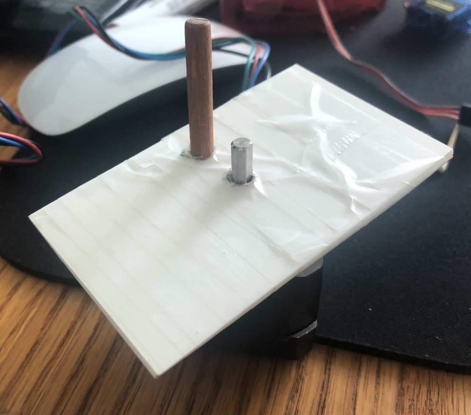
My first attempt involved taping a bunch of business cards together (to create something more or less sturdy), to which I would then attach a piece of wood I cut off of an old toy arrow. I drilled two holes into this business card mesh, one for the stepper motor bit, and the other for the wooden stick. While it does technically rotate, after a bit of consultation and more thought, I felt that this wouldn't be sturdy enough to move quickly and continuously bend wire.
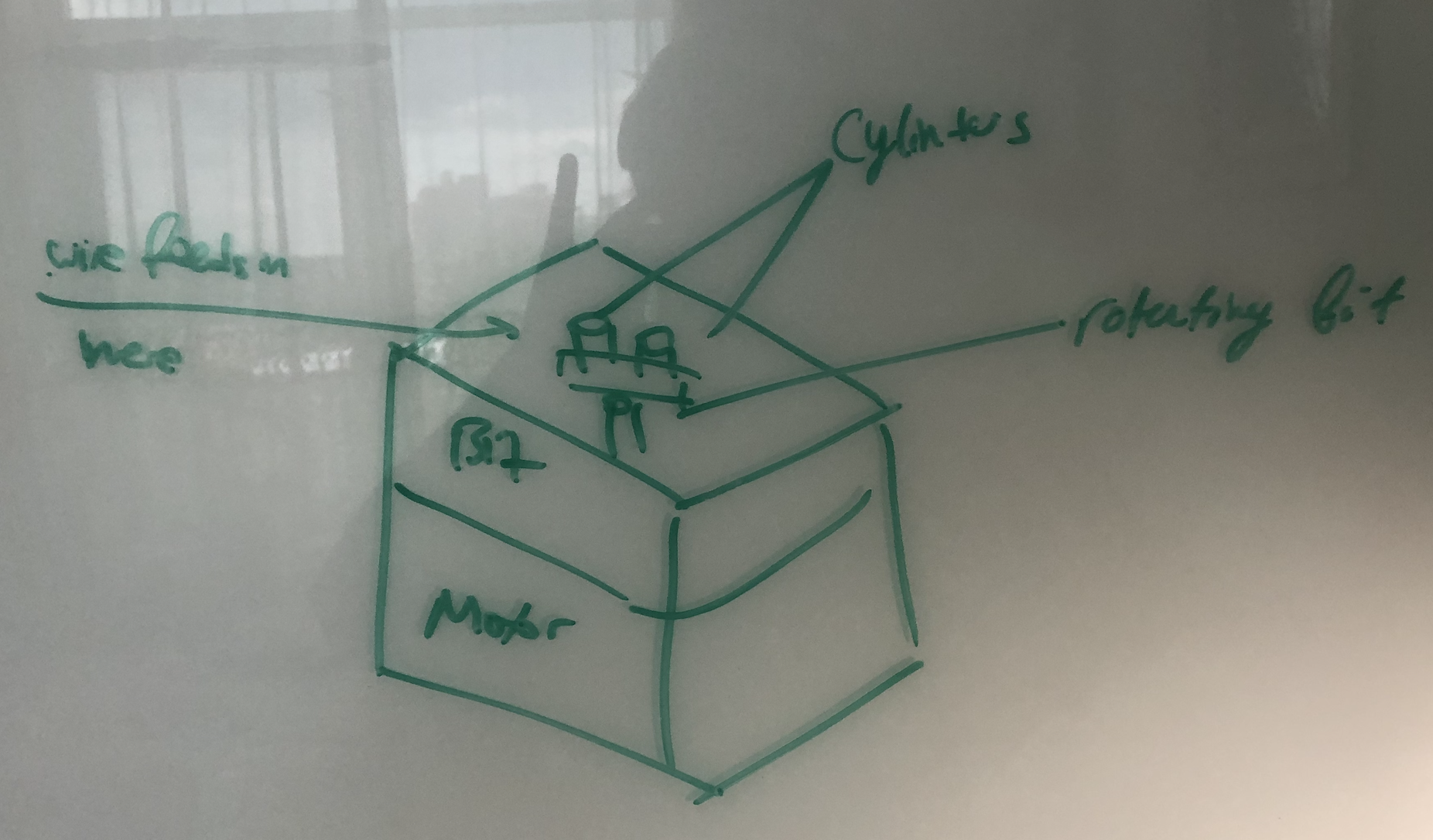
After this attempt, I settled on replicating one of the designs found on the videos that I was looking at. This would mean a small plastic bit I would screw on top of the second stepper motor with two tiny cylinders where the wire would feed. Two of them allowed for motion in 2 dimensions for the wire, which would let me bend it in either direction without much weird coding. A crude design of that is shown below.
In order to get this to work, I needed to get some 3D printed parts, which I was able to complete as soon as I got my hands on a 3D-printer.
getting the parts
Again, as described above, in order to create what I made, I would need 3D printed parts, which I modeled in Fusion360 and then exported to print on the newly-acquired 3D printer. More info on the parts themselves can be found in my Final Project tab.
the assembly
As soon as I got the 3D printed parts, the assembly was, just as with the other part, more or less feasible and straightforward. They all locked and screwed together, with only minimal glueing required for the feeder tip on the bender mechanism.
I spent a lot of time during the days I had to understand exactly how this mechanism should work and how I could get it all to work. Results are visible here in the final demonstration of the prototype and in my Final Project tab.
the code
I have been workshopping how I could code them to work, but I need to be able to visualize it to really understand how it works. I was able, however, to drive two stepper motors during the breakout room sections, so I was not worried about actually getting them to drive. However, to truly get how to bend shapes, I needed the mechanism in front of me, so code will be listed here as soon as the mechanism is created. It's visible in the Final Project tab.
the result
Again, a major result of my current progress has been a thorough understanding of how these mechanisms worked, and what I would need in order to create it. An actual demonstration of a 2D wirebending mechanism will be available when I get all the parts and subsequently code it.

With this prototype completed, I was ready to completely calibrate it, create an outer shell, and finalize this as my final project for this course.
This was a rather difficult, but interesting endeavor that consumed a lot of time and patience. In fact, it got me thinking about a potential edit to my final project, which would be a better culmination of the work that I have done in this class, incorporating hardware design and creation, software coding, and remote operation through the internet. More can be found in the little description below.
potential final project edits
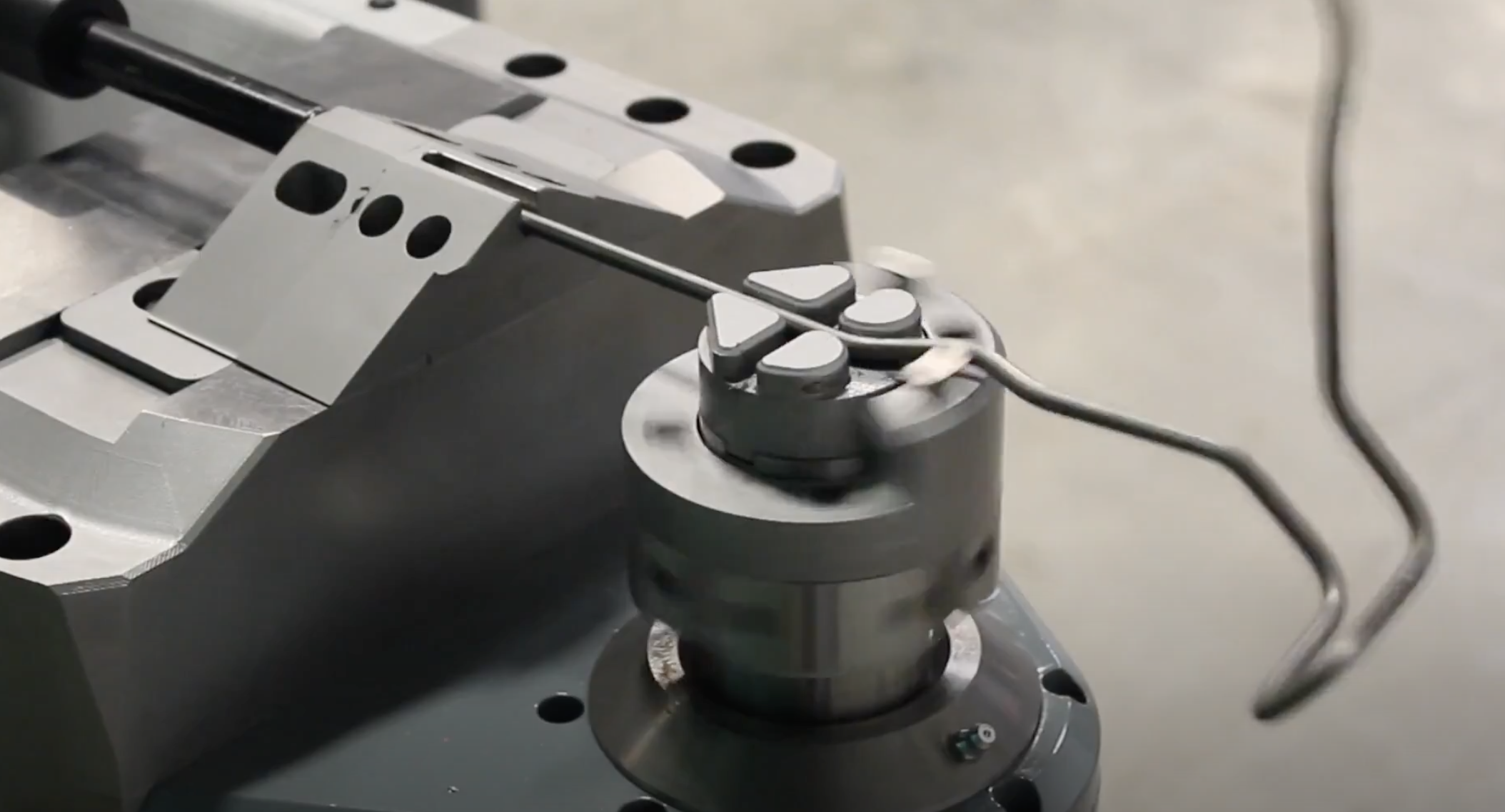
With all of this work, I actually thought of a new idea for my final project. Getting this to work would be an excellent lead-in for the new proposed final project, which would be a 3D wirebending mechanism that could move in multiple dimensions. So far, the wire does all the moving, which is cruder than the plan, but with an extra motor, I would be able to create something along the lines of what is shown in this video. Here's a cool image of what this could look like.
As soon as I could get the 2D wirebending mechanism working, abstracting up to the 3D wirebending mechanism wouldn't be the most complicated of tasks. While it is certainly a challenge that would involve a lot of building and a bit of coding, I was excited about this new project idea.
This was an overall long week, but I was able to get a lot done, even if I didn't complete the actual build in time for class. I also celebrated my birthday on Sunday, which was also quite fun. I was excited to start finishing up the materials for this course, and wrapping everything up. Over the next few days, I would have to finalize all my assignment pages (fixing anything that didn't look right, reformatting, completing outstanding assignments, etc.) and get a good chunk of my final project done. It would be a lot of work, but I am up for the challenge. In fact, with this new idea for a final project, I am quite excited to get all of that work done.
final message: 10 august, 2020
As of 10 August, 2020 (the publishing of this final bit), all documentation of this website has been finalized, and no further documentation will be added to this website. No additional photos, videos, code snippets, models, or commentary will be posted to this site. This website is meant to serve as the documentation of my learning during the Introduction to Digital Fabrication (PHYS S-12) course during Harvard Summer School 2020, and the program officially ended on 10 August. Thus, this website will no longer be edited and nothing will be added to it. This is why my biographical information may no longer be accurate at the time of reading of this page. It has been a fun run, but sadly, the course is over, and thus my documentation is also complete. Thank you to anyone and everyone who helped me along the way, and I am excited for future endeavors!