07: electronic input devices
introduction
This page details what I learned with class 7, held on 14 July, 2020. This class focused a lot on sensors and other electronic input devices. These would come in handy with controlling inputs and outputs, which is something quite useful when it comes to designing the final project (especially in my case).
the components
To understand the inputs and how they work, we need to first revisit the kit, and then understand applications of these devices and how they can be incorporated into circuits to yield results and outputs with those circuits.
revisiting the kit
To understand what electrical input devices are and how they work, we need to look back on the kit we got, and specifically some of the components in it. We looked specifically at anything in bag 2, titled "sensors".
light input
One very common form of inputs are those that deal with light, otherwise known as light sensors. There are visible light sensors, IR sensors, UV sensors, etc, though our kit really only has visible and IR sensors.
sound input
Sound inputs are also really useful when it comes to various projects and components, and typically comes in the form of a microphone. Sensors that measure sound input can also be found in the kit, and can be used to make clap-on and clap-off lights, for example. "Hey Siri" is activated through sound input in the microphone of an iPhone.
motion and force
Another very useful thing that can be measured and used as input is motion, or by extension, pressure. The kit contains a proximity sensor, as well as Velostat pressure-sensitive sheets. These can measure changes in pressure or distance, which can be used to make automatically-opening doors, for example. The kit also contains an accelerometer, which measures difference in velocity and motion, which is commonly used in smartphones for health applications.
other
There are also other sensors available in the kit and outside the kit, such as temperature sensors (thermistors). Some of these are availab in thed kit, and can be used to make other sensors.
Now, the kits have been revisited. There are, of course, many other types of sensors and inputs available elsewhere.
After reviewing the components in the kit, we are ready to have some fun with (I mean, better understand) them and put them to good use in the breakout rooms.
breakout rooms: capacitive sensors
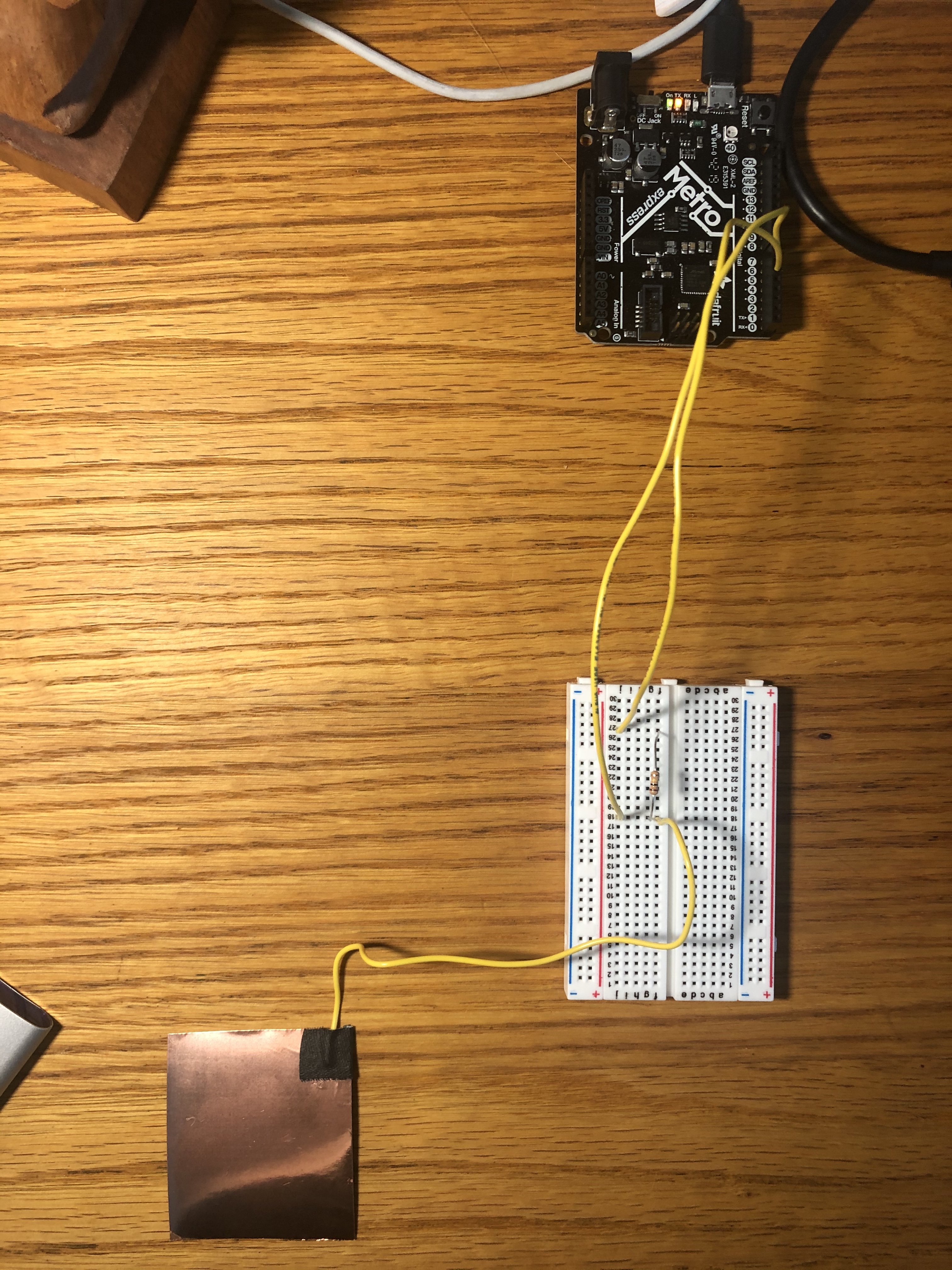
We worked with a capacitive sensor during the breakout room session. We installed the "CapacitiveSensors" library from Arduino, hooked up a circuit that looks like this, and measured outputs.
After playing around with this, we were ready for the assignment, which would involve calibration of some sensor and some measuring of some properties.
assignment
For this class's assignment, we were supposed to calibrate two things: a sensor from our kit, and a sensor that we created ourselves. Both were rather annoying and difficult, but the results are quite interesting.
calibrating sensor in the kit: Hall
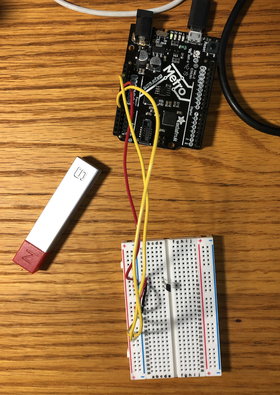
I initially wanted to calibrate the potentiometer, but after a lot of fussing around with th circuitry, I decided instead to calibrate the Hall sensor, as Robert did in his demonstration. This would provide me with a better understanding of how to wire a sensor to calibrate, as the potentiometer's pins were confusing me more than enlightening me. I used an old bar magnet I managed to to dig up.
wiring the circuit
This took a lot of trial and error, as I wasn't sure how to wire it for it to produce a result. However, after a lot of fiddling around, I figured out a way to wire it so that I could then, with some code in Arduino, measure maximum and minimum inputs.
the results
Here, I have my results for the calibration.
Here is the code I inputted into the Arduino for calibration:
                  // nothign necessary other than initialization
                  void setup(){
                     Serial.begin(9600);
                   }
                   // read the value given and delay a little bit
                   void loop(){
                     int val = analogRead(A0);  // read Hall sensor value
                     Serial.println(val);
                     delay(25);
                   }
Here is the graph that I came up with whilst calibrating the circuit:
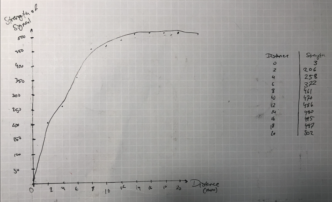
the conclusion
It was overall quite an interesting experiment, and I even had to try different magnets to get it to work. Instead of cardboard cutouts, I simply measured and found anything that was the appropriate distance.
Now that I had successfully calibrated the Hall sensor, I was ready to fabricate my own sensor and calibrate it. Unfortunately, I had way too many issues with the calibration of that sensor, so I never really came around to the completed graph.
The board was having weird issues, but they were eventually resolved.
final message: 10 august, 2020
As of 10 August, 2020 (the publishing of this final bit), all documentation of this website has been finalized, and no further documentation will be added to this website. No additional photos, videos, code snippets, models, or commentary will be posted to this site. This website is meant to serve as the documentation of my learning during the Introduction to Digital Fabrication (PHYS S-12) course during Harvard Summer School 2020, and the program officially ended on 10 August. Thus, this website will no longer be edited and nothing will be added to it. This is why my biographical information may no longer be accurate at the time of reading of this page. It has been a fun run, but sadly, the course is over, and thus my documentation is also complete. Thank you to anyone and everyone who helped me along the way, and I am excited for future endeavors!